

[2009. 9 ~ ] @ SNUST

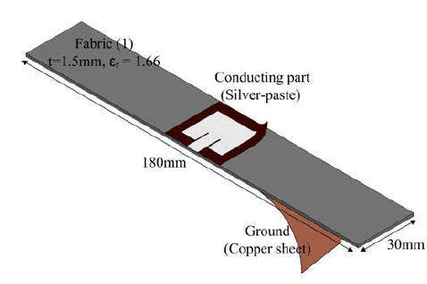
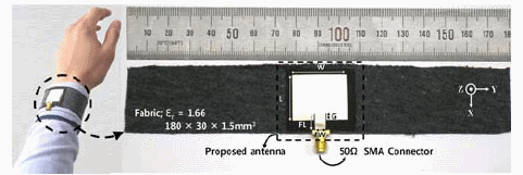
Geometry of a rectangular patch antenna
Photograph of the fabricated antenna (fabric 1)


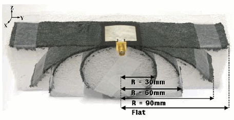
Photograph of a fabric antenna under various bent conditions (radius=30, 60, and 90 mm, and flat) (fabric 1)
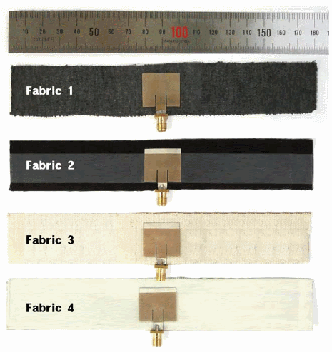
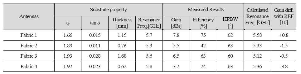
Photograph of the wearable antennas (fabrics 1-4)
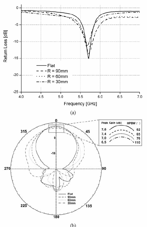
Measurement results of the fabric antenna under various bent conditions (fabric 1) (radius=30, 60, and 90 mm, and flat): (a) return losses, (b) radiation patterns in the y-z plane at 5.6 GHz
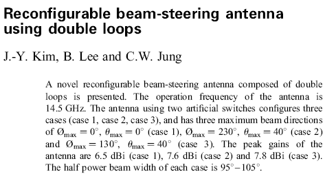
J. Kim, B. Lee, C. Jung, "Reconfigurable Beam Steering Antenna using Double Loops," IET, Electronics Letters, vol. 47, Issue 7, pp.430-431, March, 2011
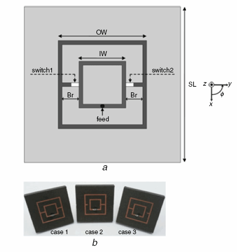
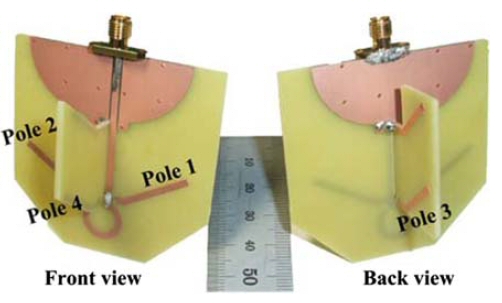
Proposed reconfigurable beam-steering antenna with two artificial switches a) Top view of proposed antenna b) Fabricated prototype antennas (cases 1, 2, 3)

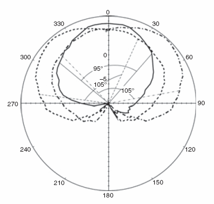
Measured radiation pattern of antenna at 14.5 GHz (u plane)
—— case 1 (Φ 0 cut) - - - - case 2 (Φ 50 cut) – . – case 3 (Φ 130 cut)
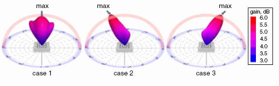
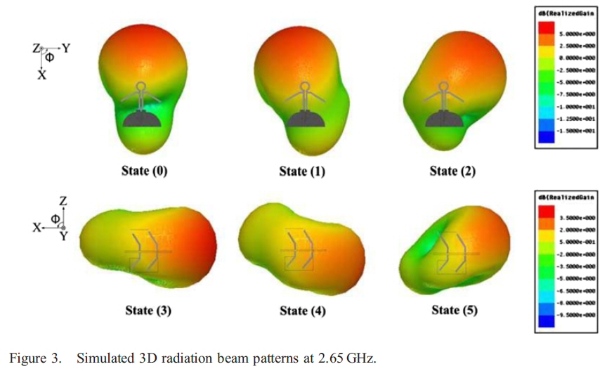
Simulated 3D radiation patterns of antenna at 14.5 GHz
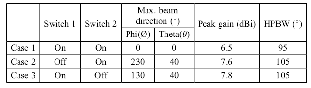
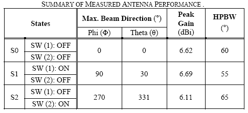
Summary of maximum beam direction, peak gain, HPBW
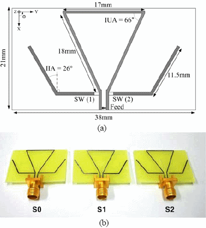
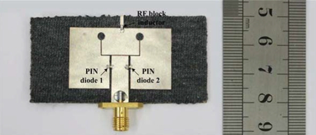
(a) Geometry of the proposed antenna that was fabricated on FR-4. (b) Photograph of the antenna fabricated on FR-4.
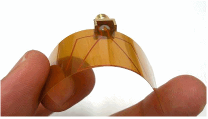
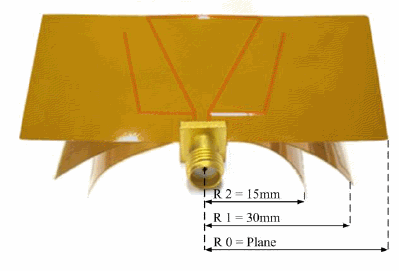
Photograph of the antenna that was fabricated on a flexible PCB under various bending conditions.
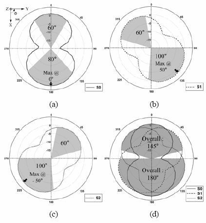
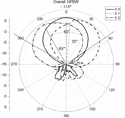
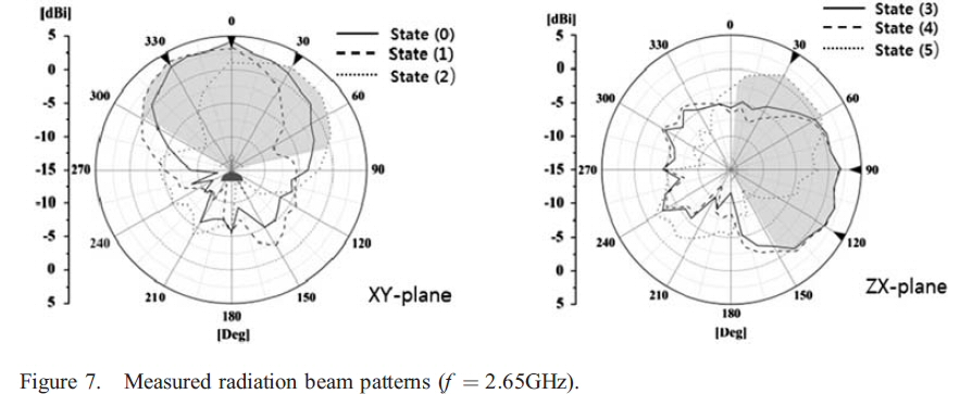
Measured radiation patterns of the antenna that was fabricated on FR-4 at 2.5 GHz (θ = 90° cut). (a) S0. (b) S1. (c) S2. (d) Overall HPBW.
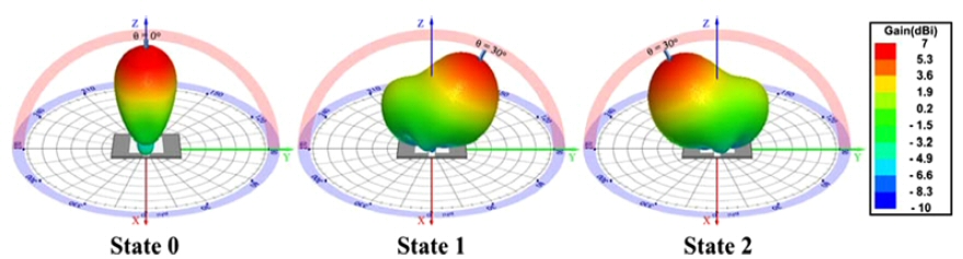
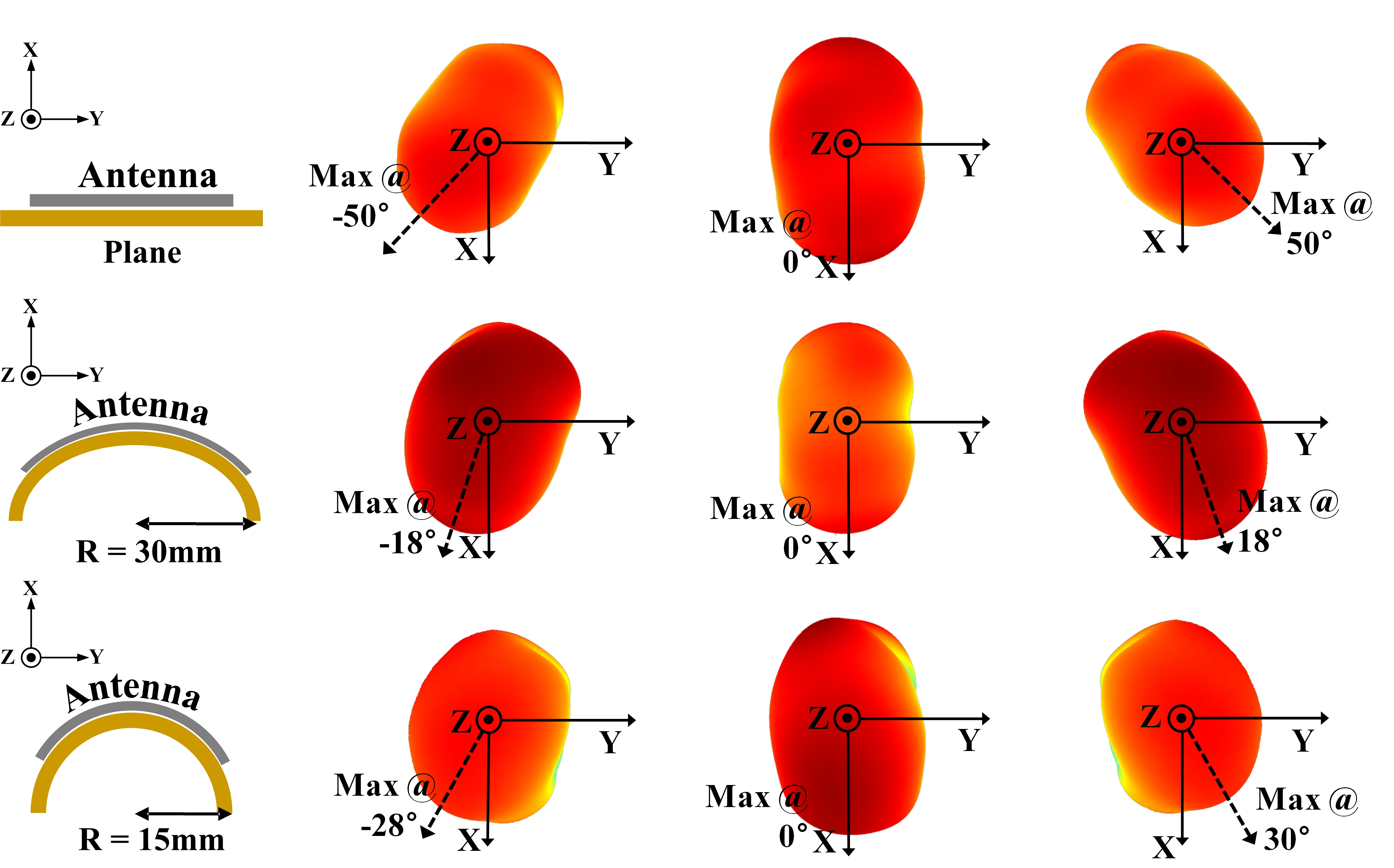
Measured radiation 3D patterns of the antenna fabricated on a flexible PCB at 2.5 GHz (θ = 90° cut).
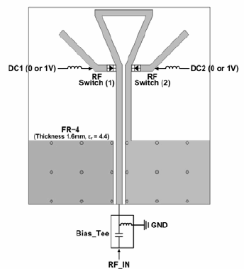
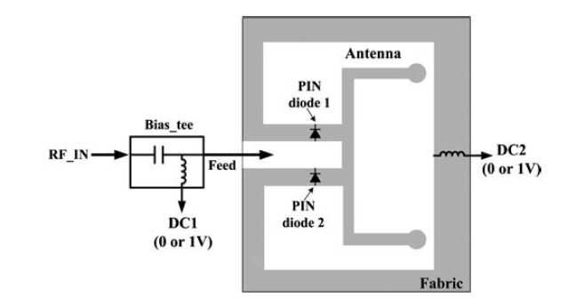
Configuration of the bias circuit using RF switches.
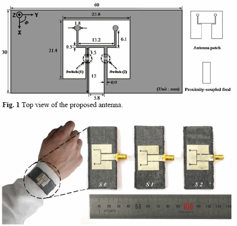
Photograph of the fabricated antenna for each state (S0, S1, and S2) and the antenna mounted on a human wrist.
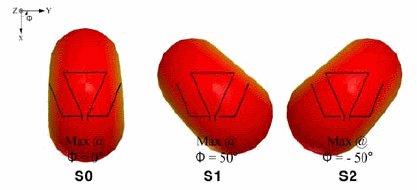
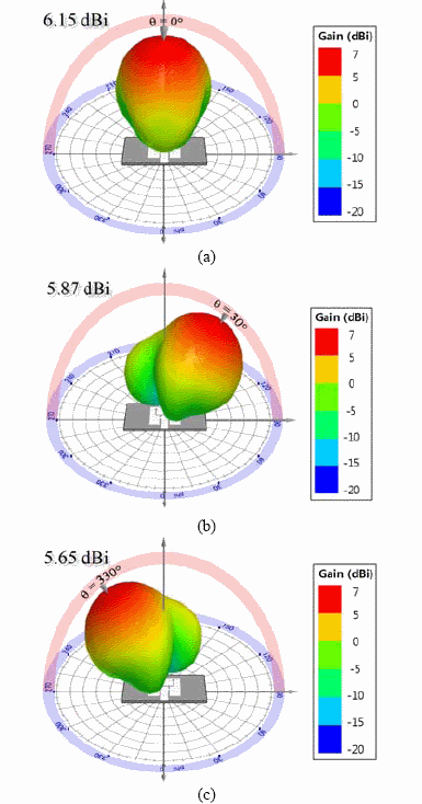
Simulated 3D radiation patterns. (a) S0, (b) S1, (c) S2.
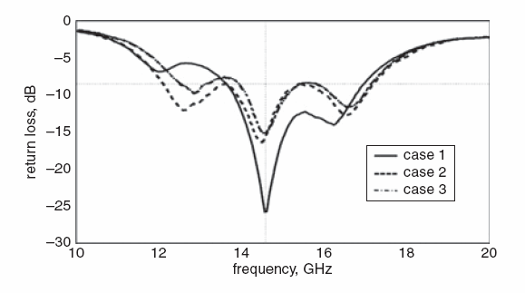
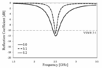
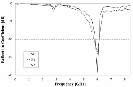
Measured return losses (S0, S1, and S2).
Measured radiation patterns and overall HPBW (yz-plane).